Transforming Drainage Rate Calculators
Units
Inputs
Result
Drainage intensity
Units
Inputs
Result
Drainage Coefficient
Units
Inputs
Result
Kirkham Coefficient
Overview
The Transforming Drainage Rate Calculators calculate three standard coefficients (drainage rates) recommended by Skaggs (2017)[1] for characterizing the hydraulics of subsurface drainage systems.
- Drainage Intensity (cm/day or in./day)
- Represents the steady state drainage rate when the water table midway between parallel drains is at the soil surface. It is a measure of the rate at which water can move through the soil to the drains.
- Drainage Coefficient (cm/day or in./day)
- Quantifies the hydraulic capacity of the drainage system. This value is the rate that the outlet works can remove water from the site.
- Kirkham Coefficient (cm/day or in./day)
- The steady subsurface drainage rate corresponding to a saturated soil profile with a shallow ponded surface.
Drainage Intensity
Drainage intensity (cm/day or in./day) is calculated by the Hooghoudt equation[2] and is dependent on the effective saturated hydraulic conductivity of the soil profile, drain depth and spacing, effective radius of the drain, and equivalent depth to the restrictive layer.
Inputs
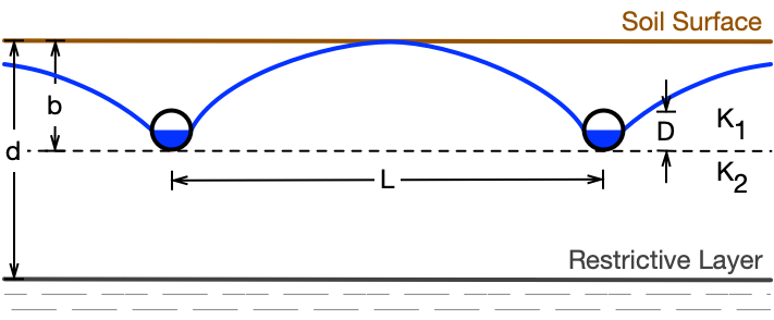
The required parameters for the drainage intensity calculator, with typical values for the Midwestern United States, and a reference diagram (Figure 1) are as follows:
- Drain spacing: The drain spacing (L) is the distance between parallel drains. Typical range: 20 to 200 ft (6 to 60 m).
- Drain depth: The drain depth (b) is the distance from the soil surface to the flow-line (bottom) of the drain. The depth of the drains affects the hydraulic head of water driving flow to the drains and the distance between the drains and the restrictive layer that is available for water flow. Typical range: 3 to 4 ft (0.9 to 1.2 m).
- Drain diameter: Different pipe sizes (D) have different opening areas, which affects water flow into the pipe and has an impact on drainage intensity. The drain diameter is used to get the effective radius from the ASABE EP260.5 standard.[3] Typical range: 3 to 6 in. (75 to 150 mm) for lateral drains.
- Depth to restrictive layer: A restrictive layer is a layer of soil that limits the vertical movement of water, which can lead to a perched water table. A restrictive layer is often considered to be a layer where the saturated hydraulic conductivity (Ksat) is less than 10% of that of the soils above it. The depth to the restrictive layer (d) affects the flow patterns of water to the drains. The drainage intensity calculator assumes that the drains are above the restrictive layer. If the restrictive layer is very shallow and the drains cannot be placed above it, a more detailed design procedure is required. If the depth to the restrictive layer is not known (deeper than the depth reported in the NRCS Web Soil Survey or deeper than any in-field sampling), an arbitrarily deep depth (for example 10 ft, as used in the NRCS Minnesota Drainage Guide) can be used to estimate the drainage intensity. Depths deeper than this will have increasingly less influence on the drainage intensity results. Typical value: known value from sampling or soil survey or an arbitrary value, e.g. 10 ft (3 m).
- Hydraulic conductivity: The saturated hydraulic conductivity (Ksat) is a measure of the ease with which the pore spaces in a saturated soil will allow water to move through that soil. The drainage intensity calculator allows for separate hydraulic conductivity values above (K1) and below (K2) the drains. Depending on the thickness of individual soil layers, weighted averages of hydraulic conductivity by layer thickness may be used for K1 and K2. The saturated hydraulic conductivity is the most important soil property affecting drainage intensity, but it is highly variable and thus difficult to find accurate, representative values. Saturated hydraulic conductivity estimates can be obtained from field measurements using the auger hole method, looking up reported values from a soil survey (the NRCS Web Soil Survey and the UC Davis California Soil Resource Lab's SoilWeb are online sources of soils data for looking up estimates of Ksat values), or from handbook data of typical values by soil texture. Saturated hydraulic conductivity is reported in a variety of units, so several units options are provided in the dropdown box.
Drainage Coefficient
Drainage coefficient (cm/day or in./day) is calculated using the Manning equation and is dependent on the size, slope, and hydraulic roughness of the drains (and where pumped outlets are used, the pumping capacity).
Inputs
The required parameters for the drainage coefficient calculator are as follows:
- Drainage area: Area drained by the pipe or tile for which the drainage coefficient is being calculated.
- Drain grade: Grade (slope) of the pipe or tile expressed as a percent.
- Drain diameter: Nominal pipe/tile diameter.
- Drain material: Selection box for the pipe or tile material used to get the Manning roughness coefficient based on the ASABE EP260.5 standard[4]
Kirkham Coefficient
The Kirkham coefficient (cm/day or in./day), as proposed by Skaggs (2017), is the steady subsurface drainage rate corresponding to a saturated soil profile with a shallow ponded surface. It is calculated using equations developed by Kirkham (1957)[5].
Inputs
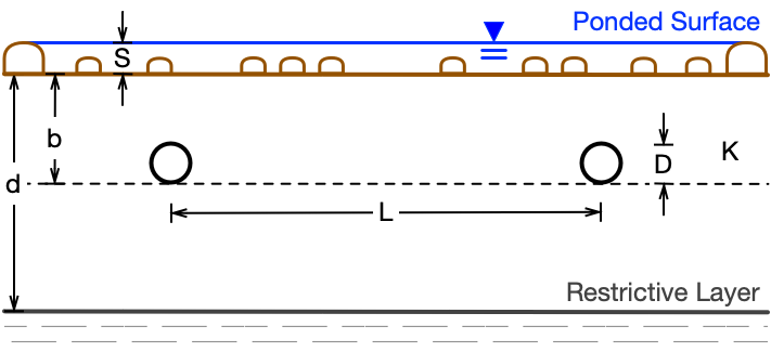
The required parameters for the Kirkham coefficient calculator are the same as those for the drainage intensity calculator with two exceptions described and shown (Figure 2) below:
- Ponded water depth: The depth of surface depressional storage (S) before runoff begins but where water can move freely across the surface toward the drains. Some general guidelines for estimating the ponded water depth are given in (Table 1).
- Hydraulic conductivity: For the Kirkham calculator, the weighted average saturated hydraulic conductivity for the entire soil profile (soil surface to restrictive layer) is used.
| Field Surface Drainage Quality | Field Description | Depressional Storage |
|---|---|---|
| Good | Surface relatively smooth and on grade so that water does not remain ponded in field after heavy rainfall. No potholes—adequate outlets. | 0.1–0.5 cm |
| Fair | Some shallow depressions, water remains in a few shallow pools after heavy rainfall. Micro-storage caused by disking or cultivation may cause surface to be only fair even when field surface is on grade. | 0.6–1.5 cm |
| Poor | Many depressions or potholes of varying depth. Widespread ponding of water after heavy rainfall or inadequate surface outlets, such as berms around field ditches or very rough surface, such as directly after plowing. | 1.6–2.5 cm or greater |
Equations
Hooghoudt equation
The Hooghoudt equation used to calculate the drainage intensity under steady state conditions is:
where the equivalent depth (de) can be computed using equations developed by van Der Molen and Wesseling (1991)[7]:

in which:

for x > 0.5. For smaller values of x, G(x) can be approximated by:
- where:
- b = the drain depth (m or ft),
- d = the depth to the restrictive layer (m or ft),
- DI = drainage intensity (m/day or ft/day),
- K1 = the saturated hydraulic conductivity above the drains (m/day or ft/day),
- K2 = the saturated hydraulic conductivity below the drains (m/day or ft/day),
- L = the drain spacing (m or ft),
- r = the effective radius of the drain (m or ft).
Manning equation
The Manning equation for a pipe flowing just full at the outlet under gravity flow (the design hydraulic capacity) for both metric (SI) and U.S. customary units can be written as:

- where:
- D = the pipe diameter (m or ft),
- n = the Manning roughness coefficient that represents the resistance to flow in the pipe and is related to the pipe material,
- Q = the flow rate (m3/s or ft3/s),
- S = the pipe grade (slope) as a percent.
The drainage coefficient (DC) is then found by dividing the flow rate by the area drained (A) as follows:
with appropriate unit conversions to express DC in either cm/day or in./day.
Kirkham equation
The Kirkham equation for the steady subsurface drainage rate with a saturated profile and shallow ponded surface is:
in which:

- where:
- b = the drain depth (m or ft),
- d = the depth to the restrictive layer (m or ft),
- K = the saturated hydraulic conductivity (m/day or ft/day),
- L = the drain spacing (m or ft),
- q = the Kirkham coefficient (m/day or ft/day),
- r = the effective radius of the drain (m or ft),
- S = the ponded water depth (m or ft).
[1]Skaggs, R. W. (2017). Coefficients for quantifying subsurface drainage rates. Appl. Eng. Agric., 33(6), 793–799. doi:10.13031/aea.12302 ↩
[2]Bouwer, H., & van Schilfgaarde, J. (1963). Simplified method of predicting fall of water table in drained land. Trans. ASAE, 6(4), 288–291. doi:10.13031/2013.40893 ↩
[3]ASABE Standards. (2015). EP260.5: Design and construction of subsurface drainage systems on agricultural lands in humid areas. St. Joseph, MI: ASABE. Available from the ASABE Technical Library ↩
[4]Ibid. ↩
[5]Kirkham, D. (1957). Theory of land drainage. In J. N. Luthin (Ed.), Drainage of agricultural lands (pp. 139-181). Madison, WI: ASA. doi:10.2134/agronmonogr7 ↩
[6]Skaggs, R. W. (1980). Drainmod reference report: Methods for design and evaluation of drainage-water management systems for soils with high water tables. Ft. Worth, TX: USDA-NRCS, National Technical Ctr. Retrieved from: https://www.bae.ncsu.edu/agricultural-water-management/drainmod/manuals/ ↩
[7]van der Molen, W. H., & Wesseling, J. (1991). A solution in closed form and a series solution to replace the tables for thickness of the equivalent layer in Hooghoudt's drain spacing formula. Agric. Water Manage., 19(1), 1–16. doi:10.1016/0378-3774(91)90058-Q ↩


Transforming Drainage Rate Calculators
Version 1.0Purpose
The Transforming Drainage Rate Calculators calculate three standard coefficients recommended for characterizing the hydraulics of subsurface drainage systems.[1]Contributors
Planning and Management
Jane Frankenberger, Professor and Ben Reinhart, Project ManagerDepartment of Agricultural and Biological Engineering, Purdue University
Programming
Chris Hay, Sr. Research ScientistIowa Soybean Association
Acknowledgements
This material is based upon work that is supported by the National Institute of Food and Agriculture, U.S. Department of Agriculture, under award number 2015-68007-23193, "Managing Water for Increased Resiliency of Drained Agricultural Landscapes." Any opinions, findings, conclusions, or recommendations expressed in this publication are those of the author(s) and do not necessarily reflect the view of the U.S. Department of Agriculture. Partially funded by the soybean checkoff through the Iowa Soybean Association.© 2020 Iowa Soybean Association. Licensed under the Educational Community License, Version 2.0.
[1]Skaggs, R. W. (2017). Coefficients for Quantifying Subsurface Drainage Rates. Applied Engineering in Agriculture, 33(6), 793–799. doi:10.13031/aea.12302 ↩